MECHANICAL LAYOUT · CAMERAS · ELECTRONICS
Inside the machine.
Explore a reconstruction of the prototype. Hover over a component to inspect its role, or switch views to see how the assemblies fit together.
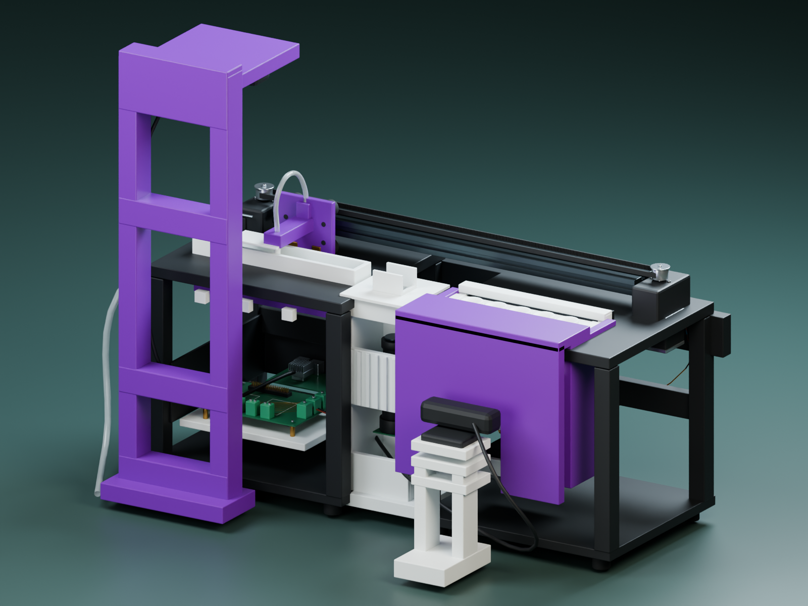 ASSEMBLED / PROTOTYPE RECONSTRUCTION
The complete handling platform. Drag to orbit; pinch or scroll over the model to zoom.
Download this GLB ↓Illustrated sequence.
Not a measured cycle time.
Transfer the fly.
Then slide the imaging lid.
The cover rides on the nozzle carriage; the imaging chamber stays fixed. Hover over a step to inspect it up close.
Mechanism documented in the report ↗Vacuum lifts one fly from the sedated loading channel.
PHOTOGRAPHS + FINAL REPORT
Prototype and reconstruction.
Compare the model with the real build. Dimensions documented in the report set the scale; other dimensions are estimates.
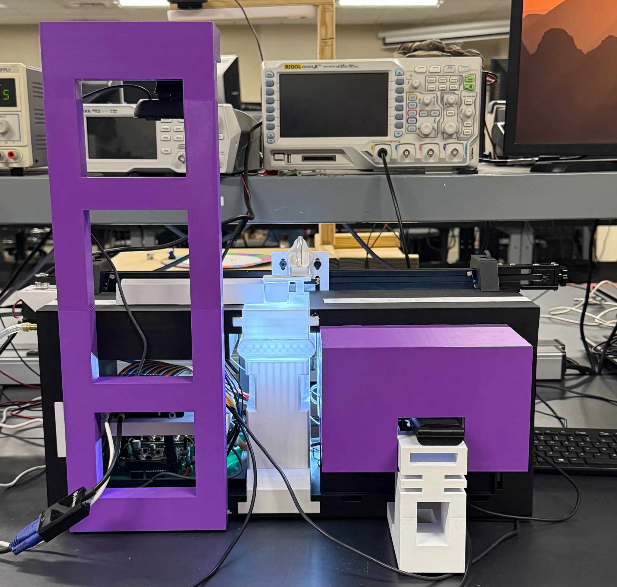
What is documented—and what is reconstructed? +
- 500 mm 2040 aluminum rail — specified rail kit in the final report BOM.
- 2 mm belt pitch / one horizontal axis — documented motion architecture.
- 19.5 mm nozzle datum / 2.0 mm opening — reported nozzle geometry.
- Five physical vial positions — final assembly drawing; labels do not assume destination assignments.
Table size, tower proportions, vial dimensions and spacing, board placement, hidden wiring, and enclosure internals are photo-informed estimates. The cutaway removes panels; this is a visual reconstruction, not manufacturing CAD or a verified digital twin. Final report ↗
10-SECOND OPERATION STUDY
Place. Cover. Image. Transfer.
The fly rests on acrylic while the carriage’s side lid closes the imaging chamber. The nozzle then realigns, repicks, and transfers it to a vial. Timing is illustrative, not measured.
01 / Reference assembly
Purple and white printed structures, black aluminum rail.
Open full-resolution render ↗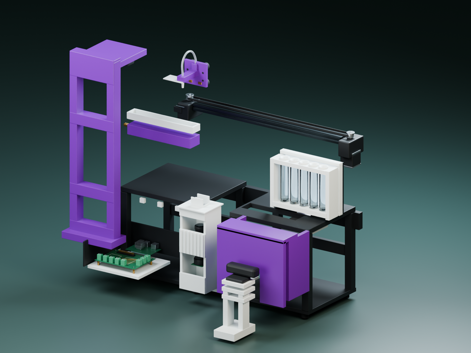
02 / Exploded assemblies
The same parts, separated by functional assembly.
Open full-resolution render ↗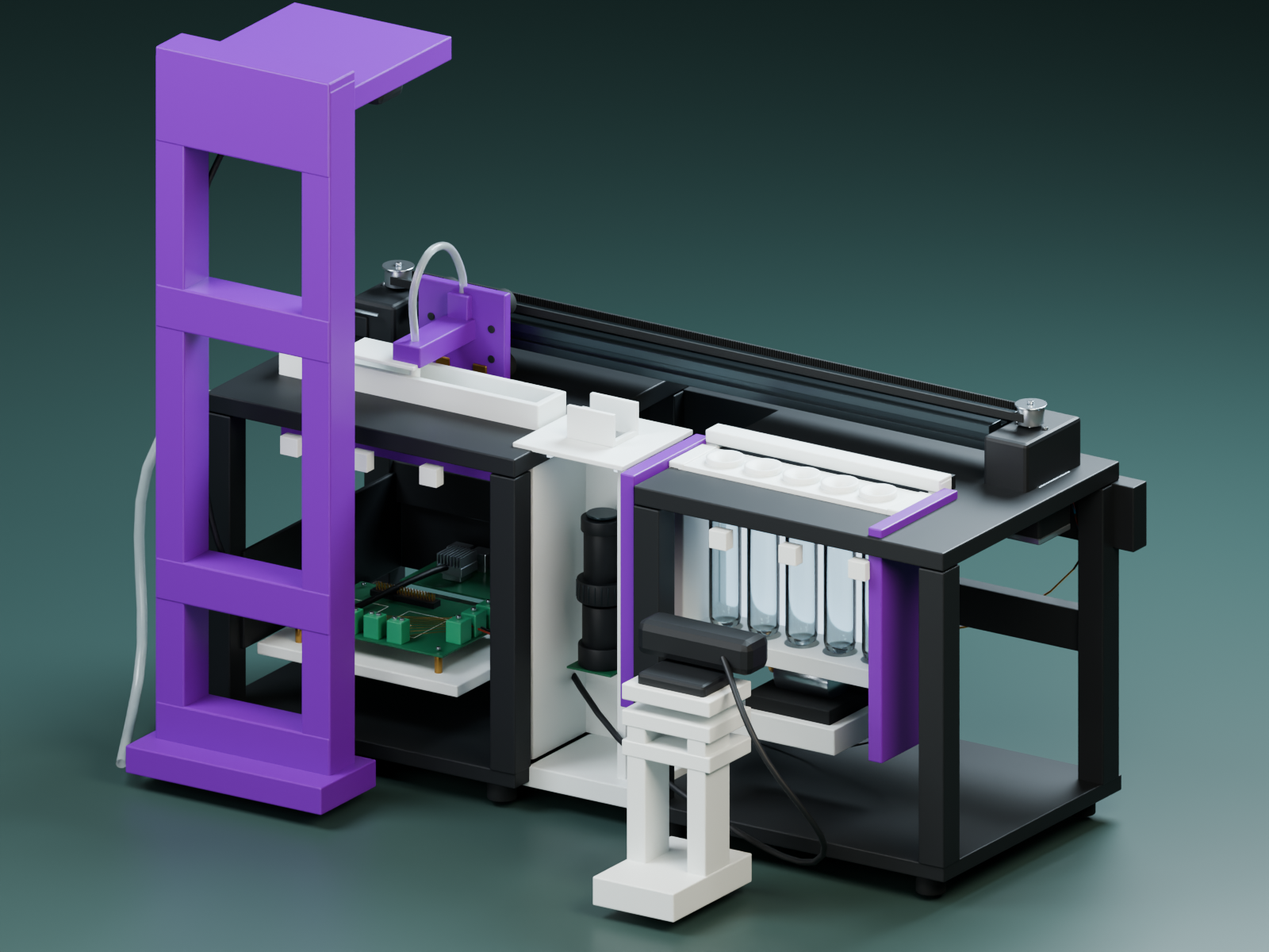
03 / Open-panel cutaway
Optics, vial rack, backlight, and electronics revealed.
Open full-resolution render ↗